The design proposal consists of a radar housing and mounting bracket. Key features of the design include:
• Two-axis angle adjustment.
• Protractor for determining the angle of both axes.
• Locking of angles, tightening using standard tools.
• Mounting on most surfaces using two conveniently placed holes.
• Feedback lights for communicating unit status.
• Backside flange for dissipating heat.
• Standard M8 contacts for connecting the radar using a variety of different communication protocols.
• Metal for robustness and plastic for allowing radar signals to pass through.
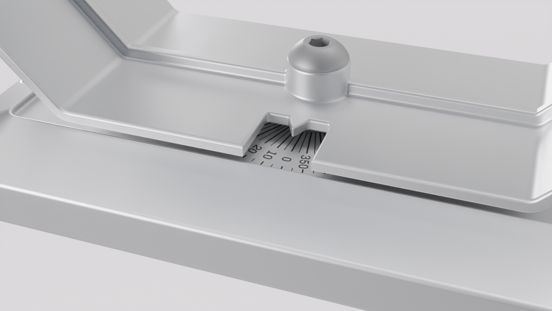
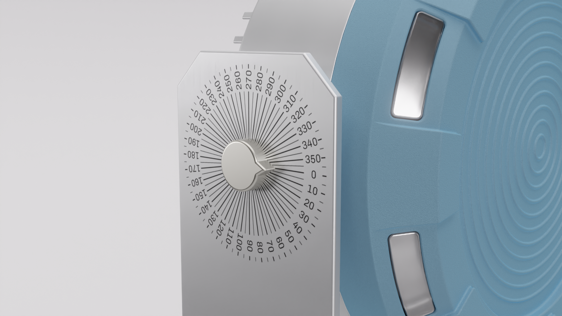
The different feedback light modes are shown below and are as follows:
• White. Normal operation.
• Flashing yellow. Warning, person in warning zone.
• Red. Stop, a person has entered a stop zone.
• Blue. Connected, configuration device connected to radar.
• Spinning blue. Uploading, new configuration uploading.
• Flashing red. Faliure, attention needed.
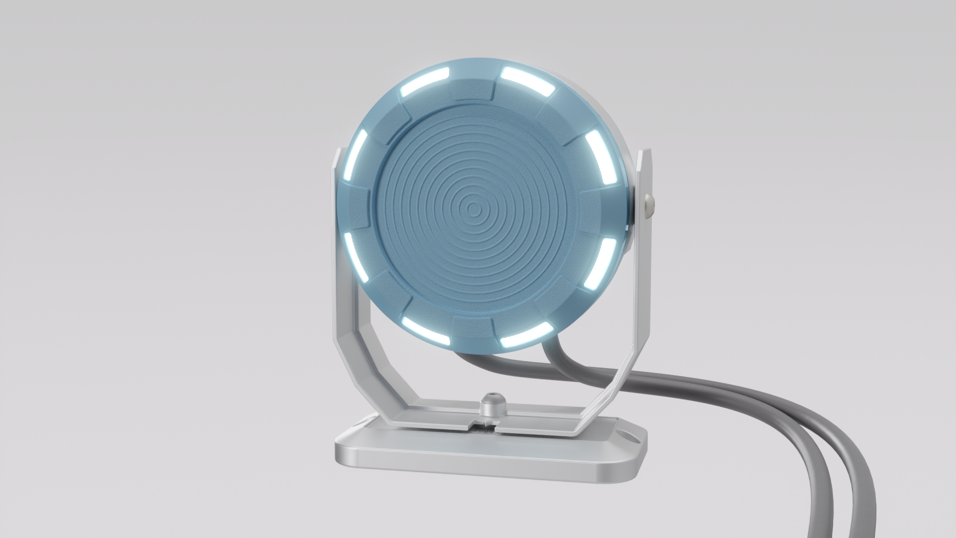
Normal operation
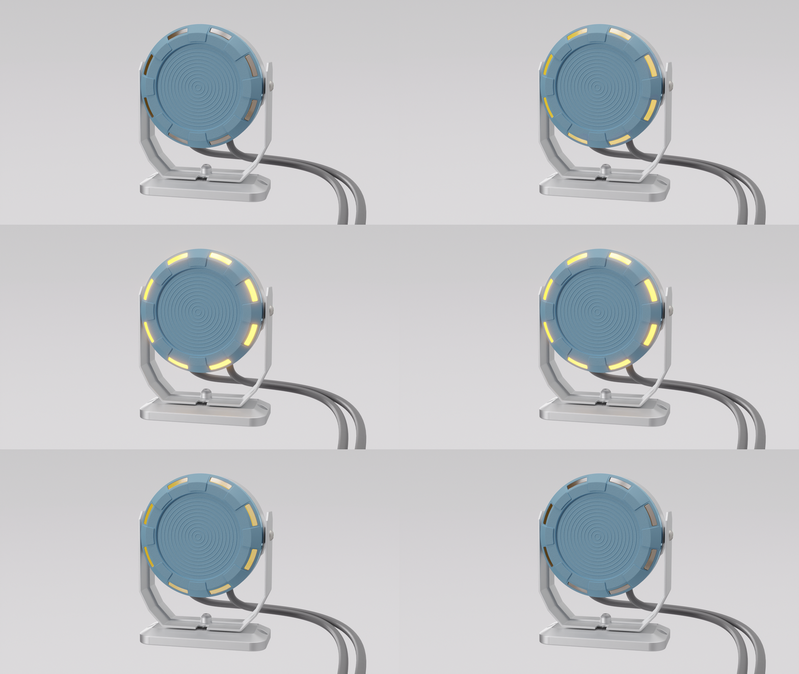
Warning (Person in warning zone)
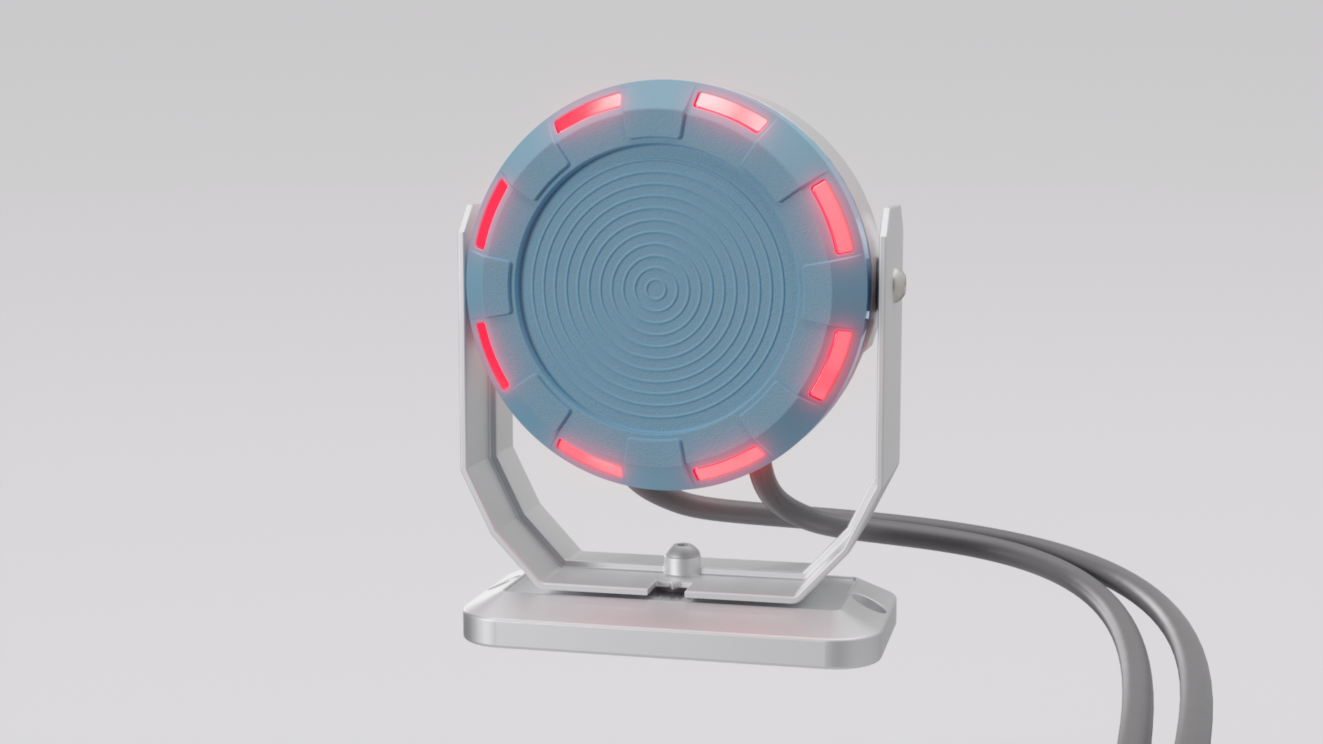
Stop (Person has entered stop zone)
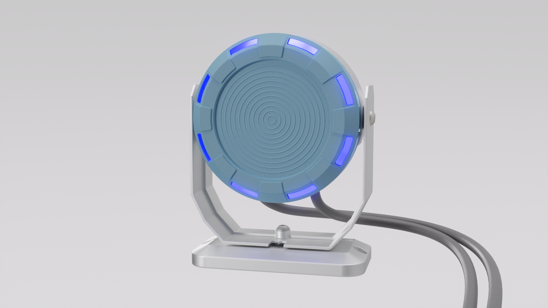
Connected (Configuration device connected to radar)
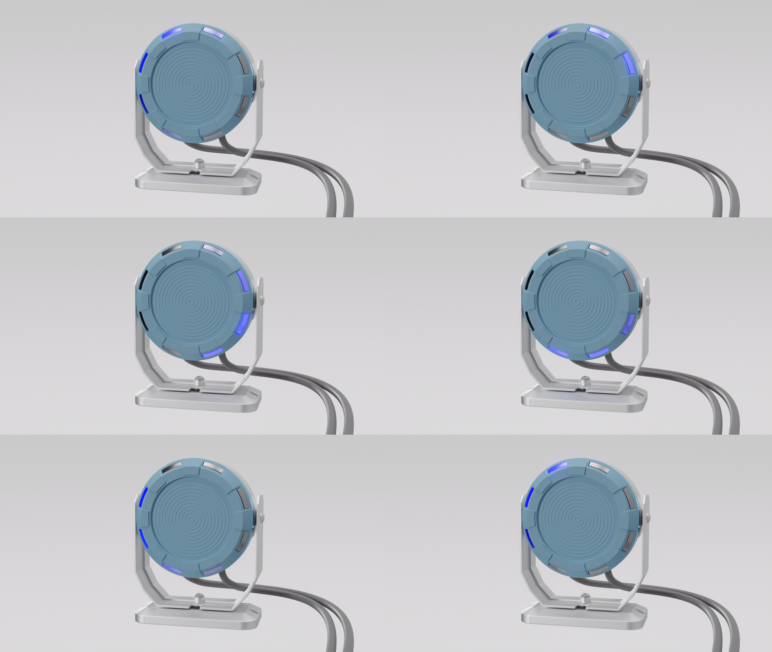
Uploading (New configuration uploading)
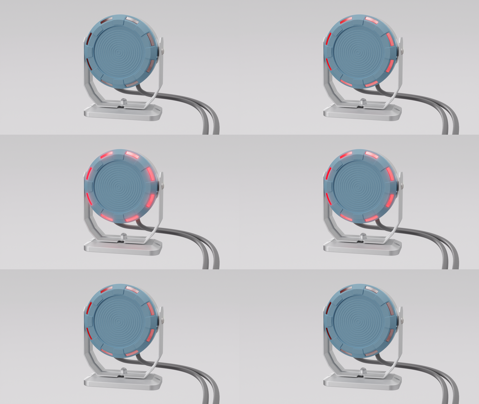
Failiure (Attention needed)
This video demonstrates how the radar could be implemented in a robot cell context.
A short video showcasing safety radar implementation.